Skip to projects

Available — DFW

02 / Curated archive

06

Selected project threads

Other Projects

Evidence lives in the iterations.

A selective archive of boards, scan failures, fixtures, fit checks, and finish experiments—the physical record between first attempt and final part.

Project 01

Fabricated + partially tested

DSP Revision 1

My first custom mixed-signal DSP/audio PCB and the starting point for the revision series. It exposed weaknesses in clocking, grounding, codec integration, PCB layout, and overall system structure that directly informed the later boards.

Tools / Processes

  • KiCad
  • Oscilloscope
  • Bench PSU
  • Hand / SMD soldering
  • Hot-air rework
  • PCB debugging / rework

Process record 06

Drag, swipe, or scroll horizontally

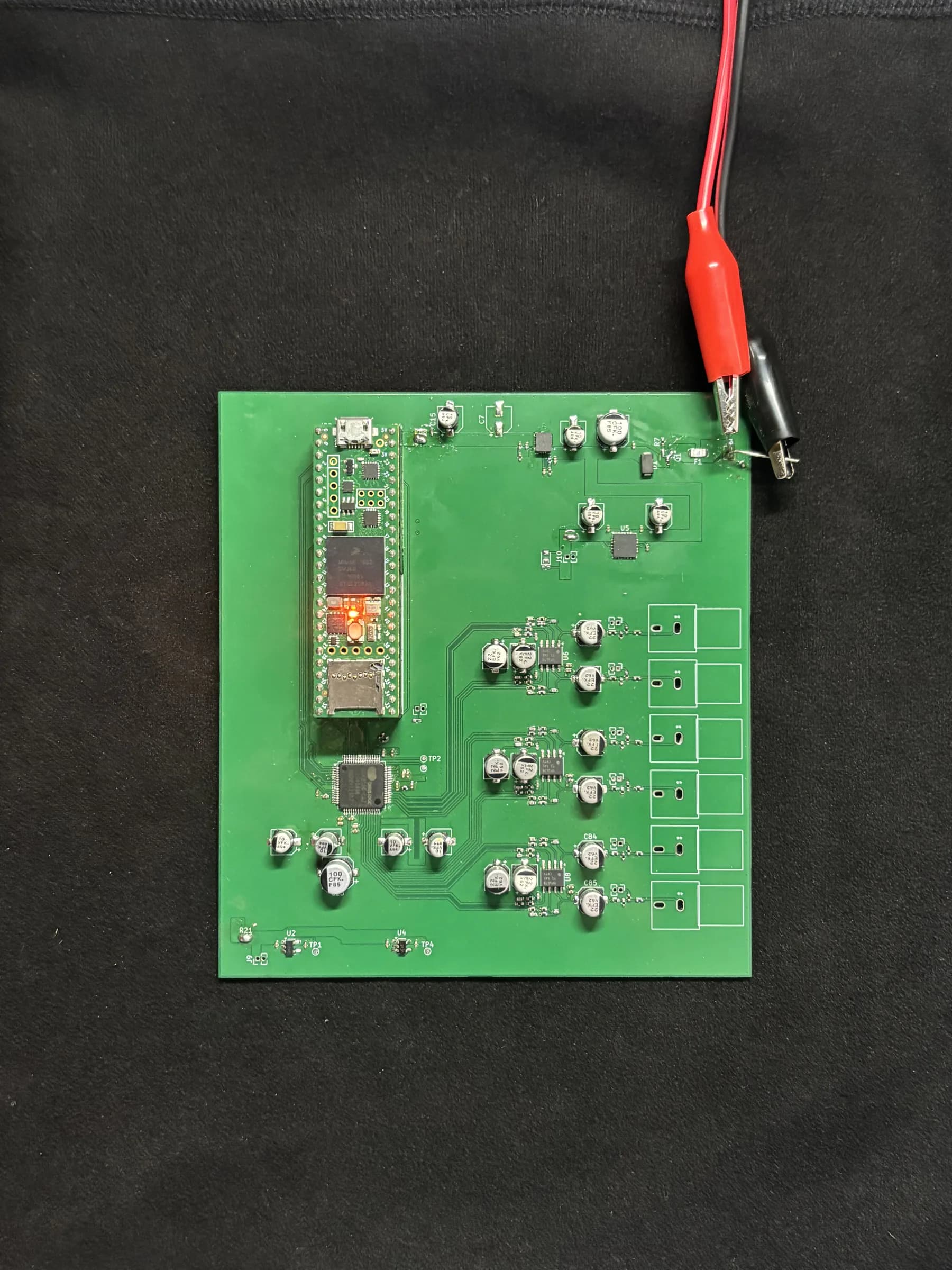
  • Populated DSP Revision 1 PCB on a work surface with test leads attached.
    First power tests on the populated Rev 1 board.
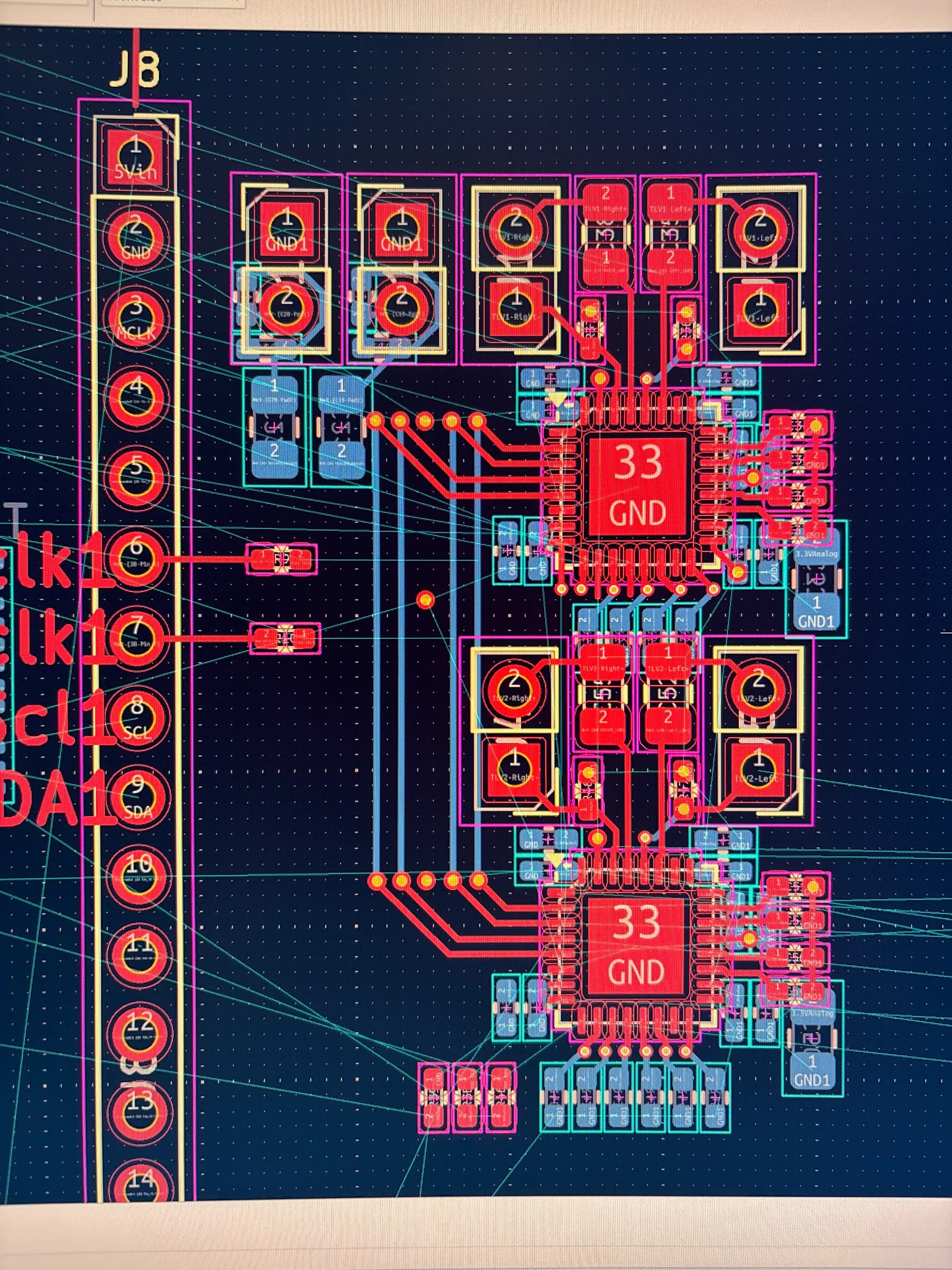
  • KiCad close-up showing two stacked codec sections of the DSP Revision 1 layout.
    Codec-channel placement and early routing.
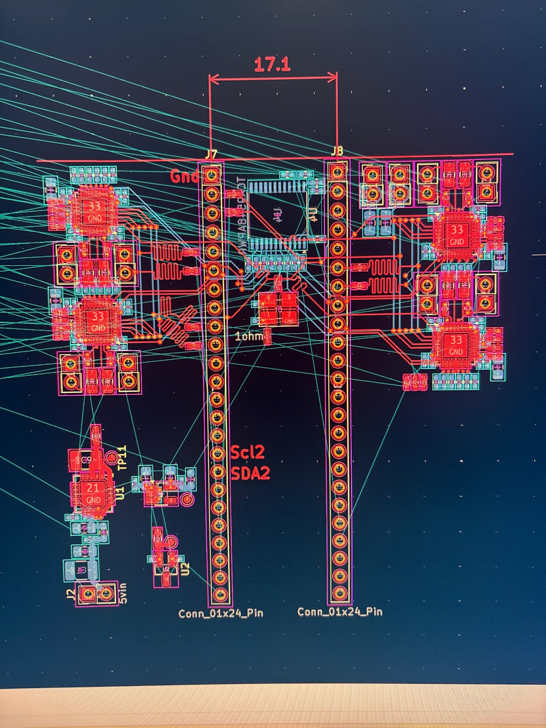
  • KiCad board layout showing the four codec sections, controller headers, and unrouted connections for DSP Revision 1.
    Whole-board placement before the remaining connections were routed.
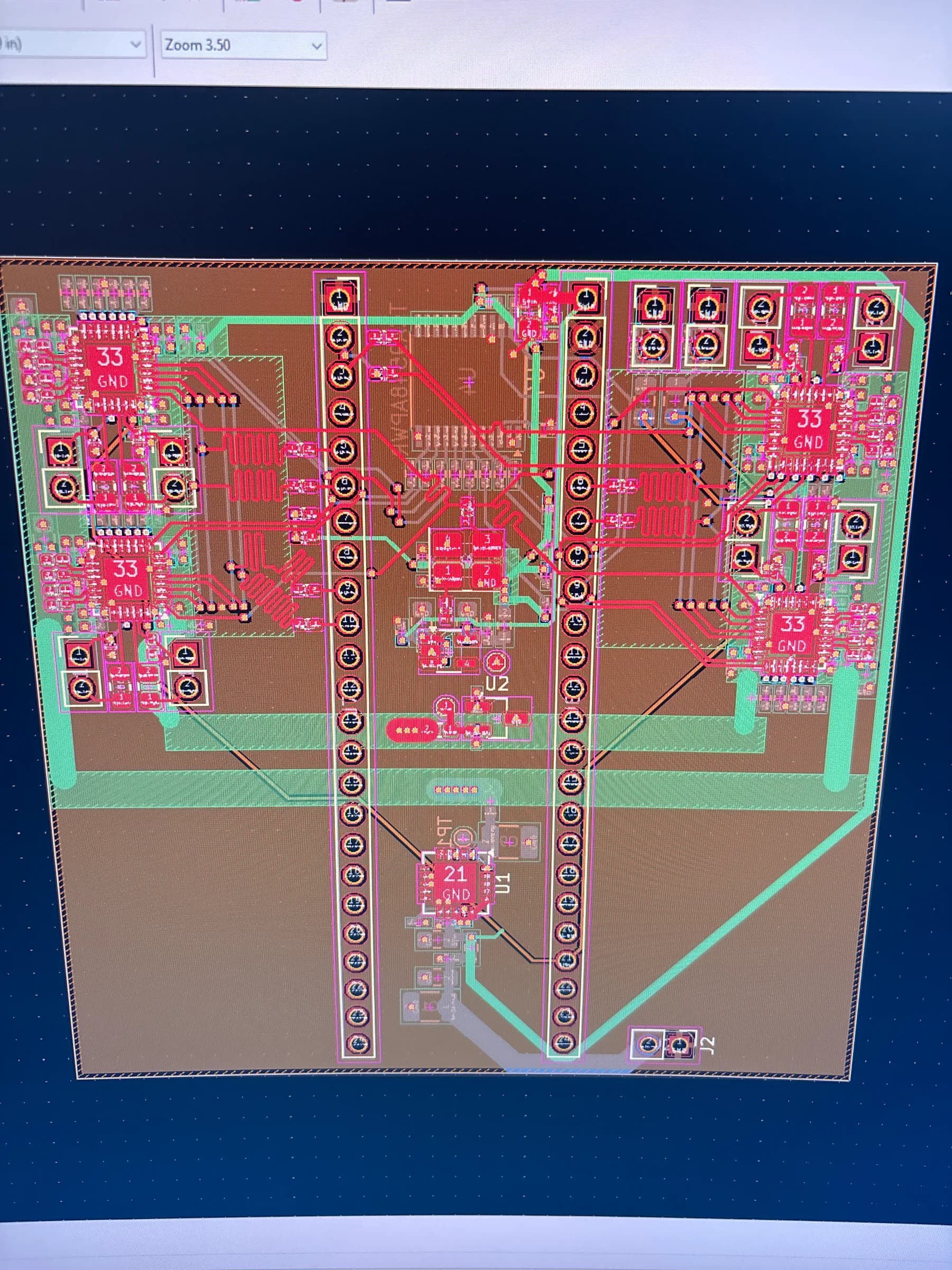
  • KiCad PCB editor showing the routed DSP Revision 1 board with copper zones and two controller headers.
    Completed board routing and copper-zone layout.
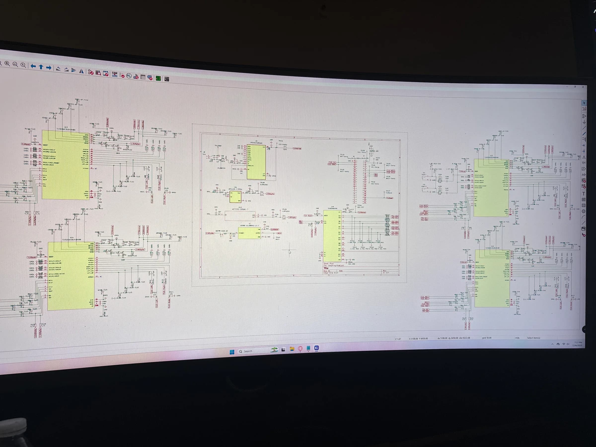
  • Wide KiCad schematic view showing four codec blocks around the central controller and power circuitry for DSP Revision 1.
    The full multi-codec system schematic.
  • Microscope bench inspection of the assembled board.

What mattered

The value of Rev 1 is the learning loop. It established the baseline and produced concrete failures and design weaknesses that could be corrected deliberately in later revisions.

View full engineering case study
Project 02

Codec online / analog output verified

DSP Revision 2

A more focused redesign of Rev 1 that simplified the architecture, improved reliability and bring-up practicality, and became the first board in the series to successfully produce and process audio.

Tools / Processes

  • KiCad
  • Oscilloscope
  • Bench PSU
  • Hand / SMD soldering
  • Hot-air rework
  • PCB debugging / rework

Process record 06

Drag, swipe, or scroll horizontally

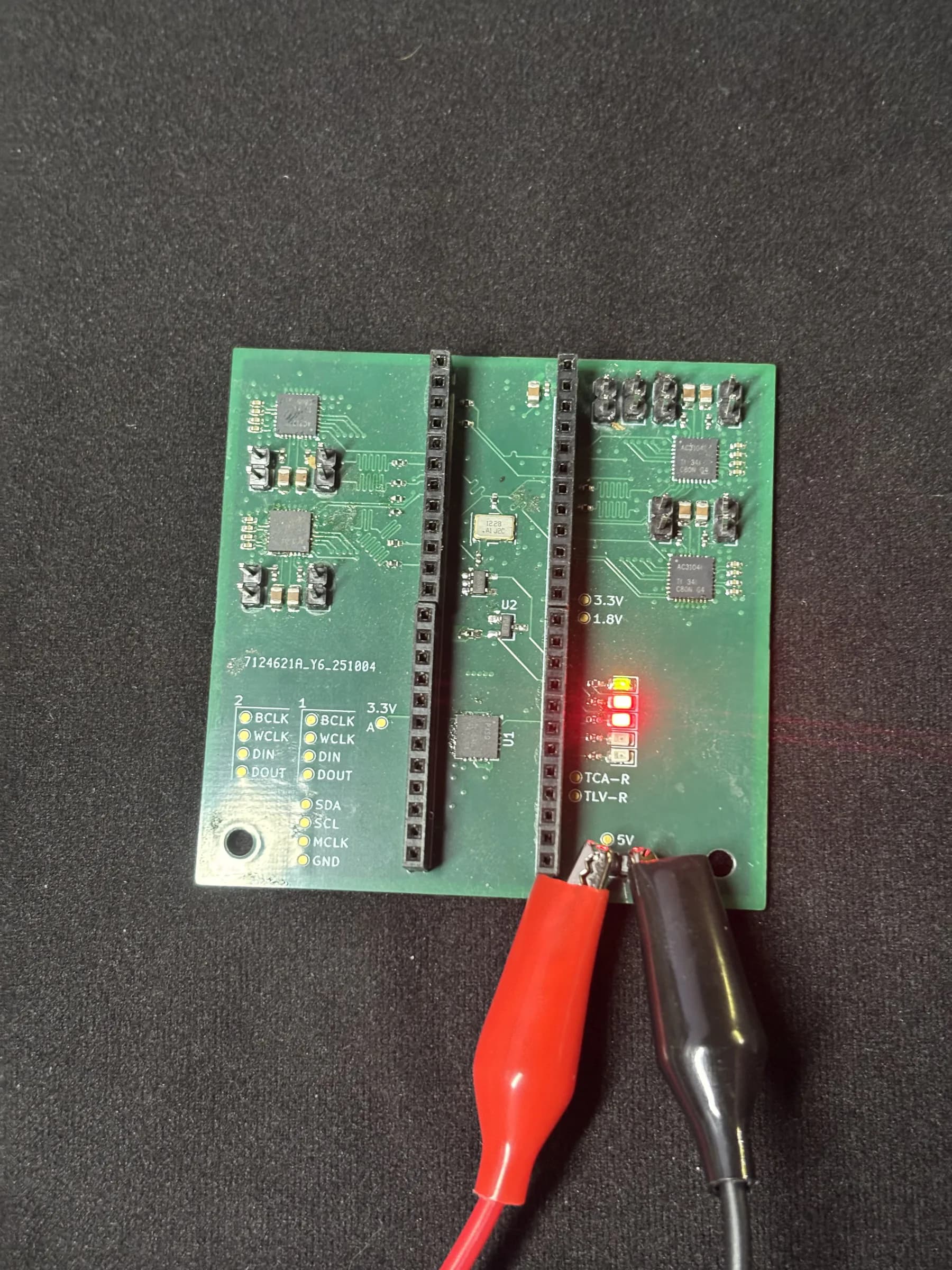
  • Populated DSP Revision 2 board powered on with red and black test leads.
    Populated Rev 2 board under power.
  • DSP Revision 2 board connected to an oscilloscope on the electronics bench.
    Board-level bring-up on the bench.
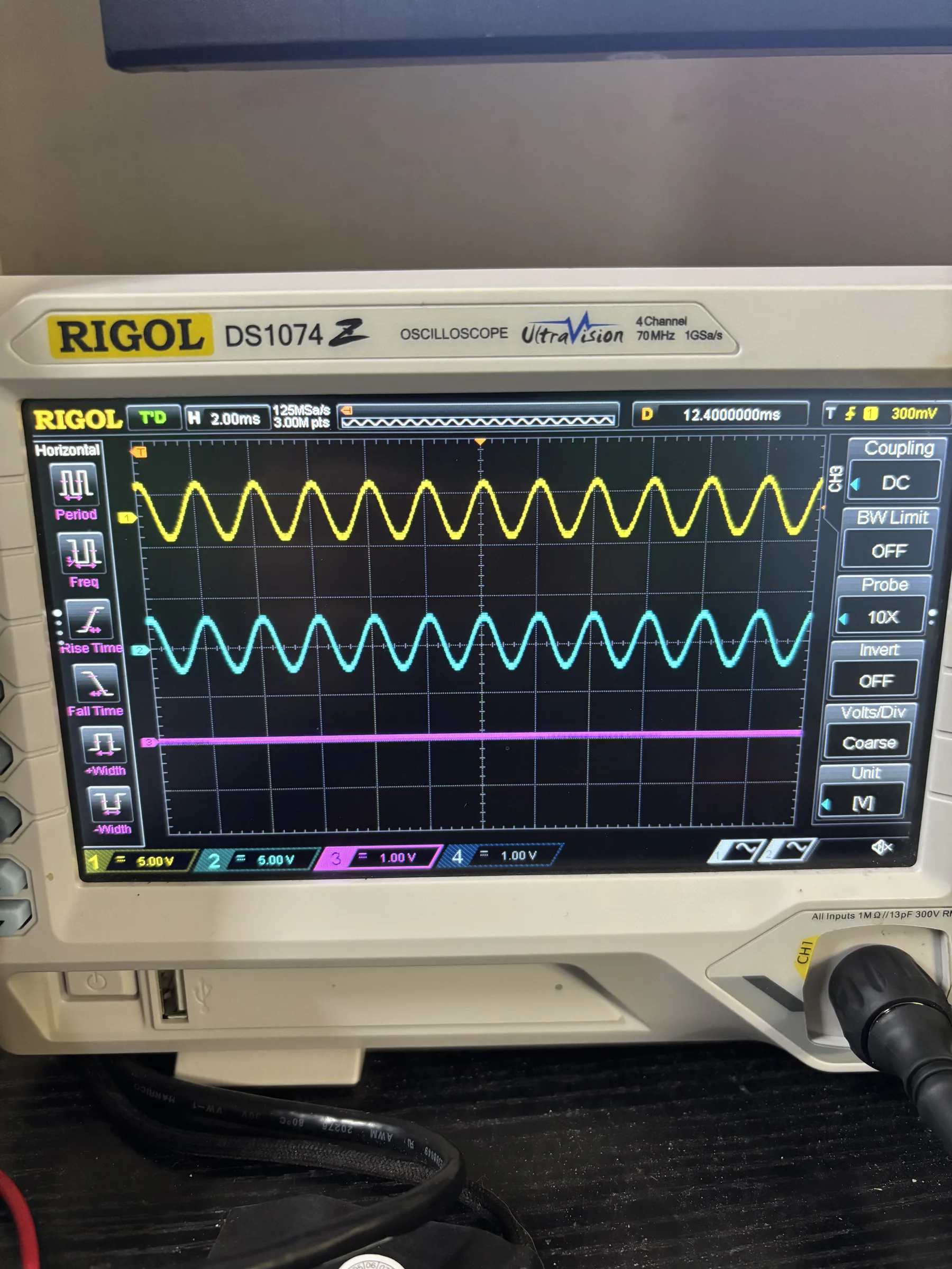
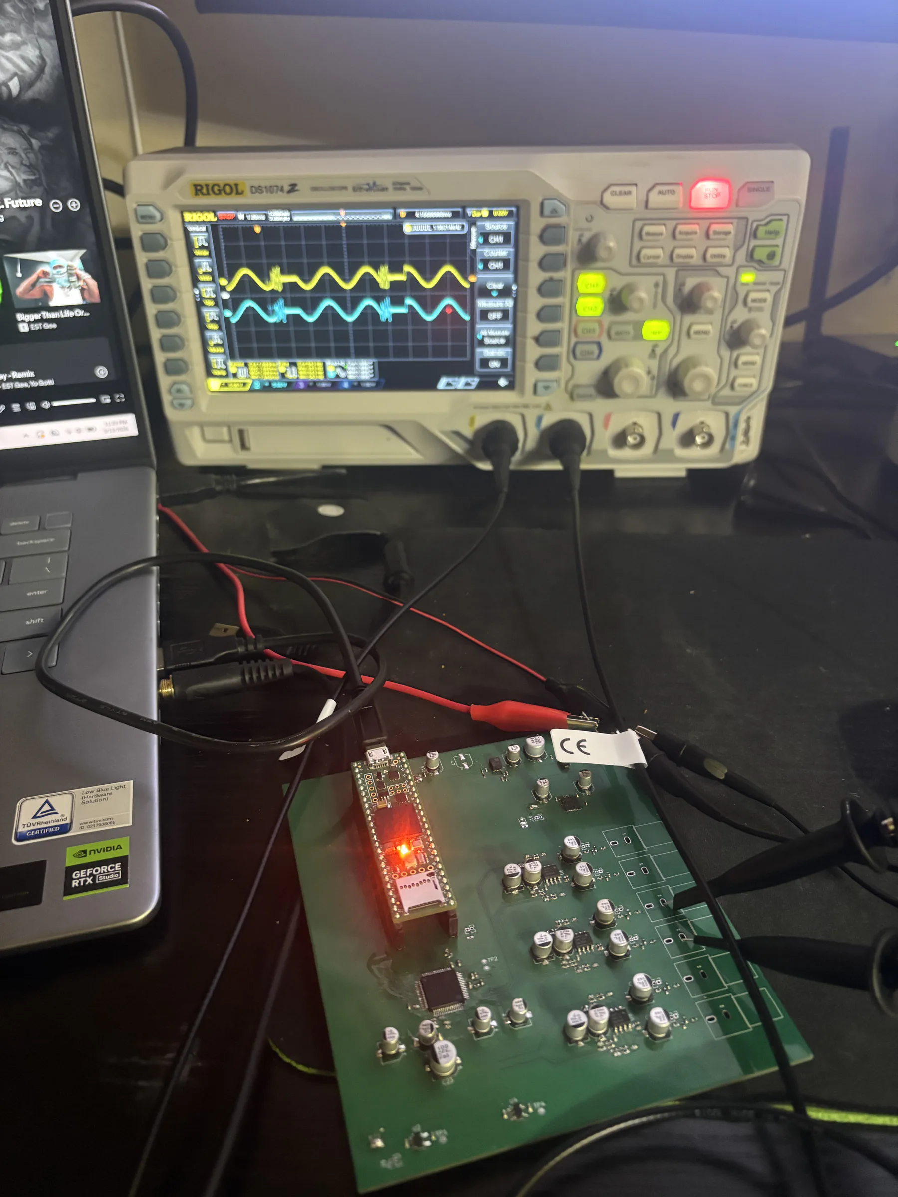
  • Oscilloscope display showing multiple waveforms measured during DSP Revision 2 bring-up.
    Bring-up waveforms captured on the oscilloscope.
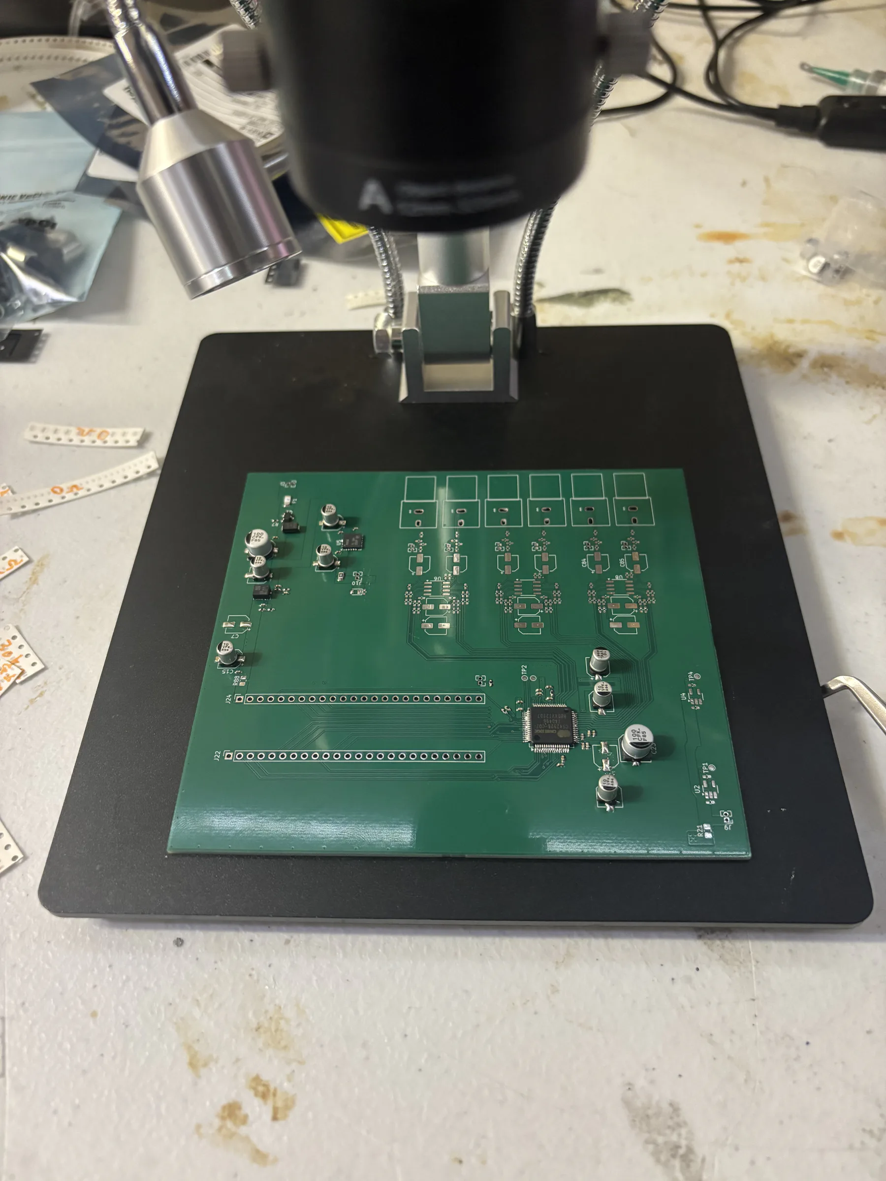
  • Partially assembled DSP Revision 2 PCB positioned under a digital microscope.
    Component placement under the microscope.
  • Close-up hand-assembly sequence—not an audio-validation demo.
  • Schematic-to-layout design review at the bench.

What mattered

Rev 2 showed that reducing unnecessary complexity and designing around bring-up and debugging could produce a much more usable system instead of simply adding features.

View full engineering case study
Project 03

Substantially assembled / never powered

Electrical bring-up, firmware integration, and performance validation remain pending.

DSP Revision 3

A more integrated evolution of the DSP platform built around a custom i.MX RT1062 implementation, CS42526 codec, ESP32 integration, and a more deliberate multilayer PCB architecture. The board reached assembly stage but was never powered, so this is design and assembly work rather than a validated result.

Tools / Processes

  • KiCad
  • Multilayer PCB architecture
  • Hand / SMD soldering
  • Hot-air rework
  • PCB assembly / rework
  • Bring-up planning

Process record 05

Drag, swipe, or scroll horizontally

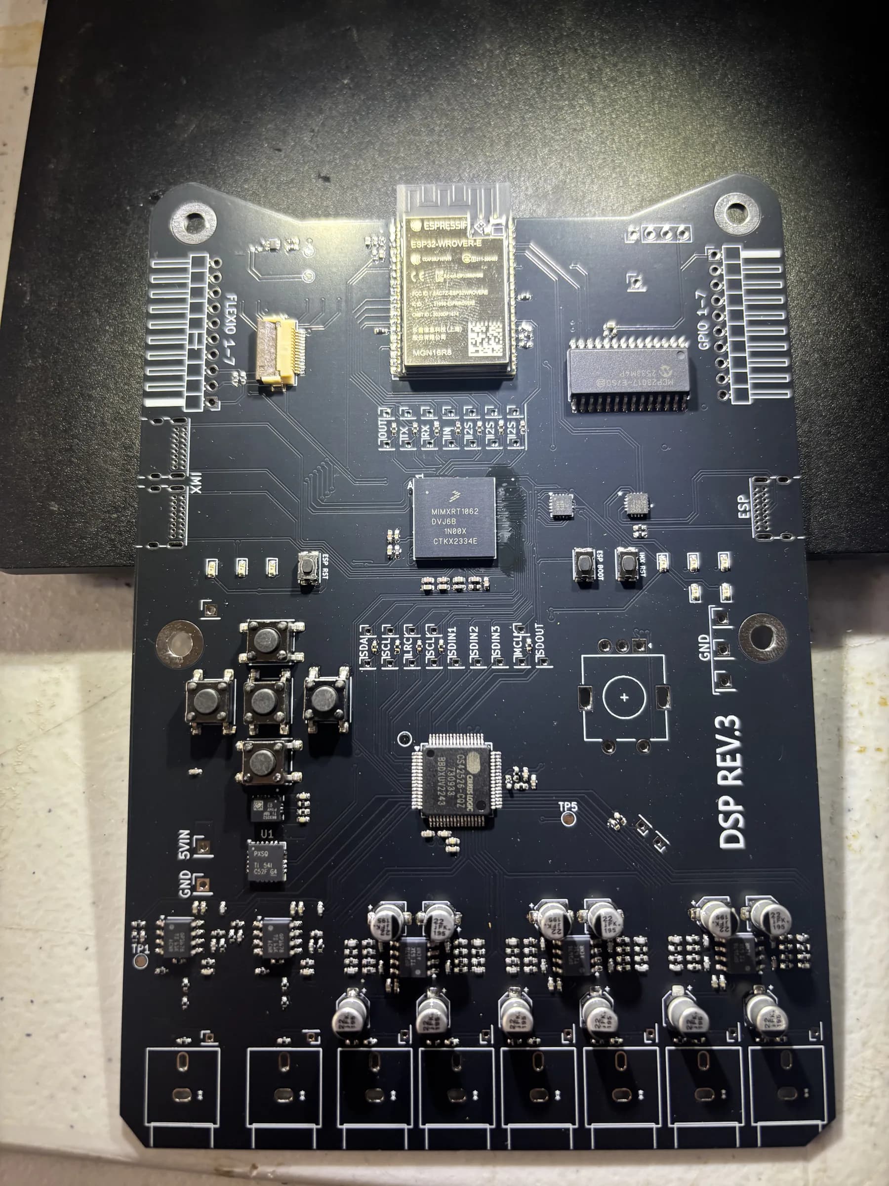
  • Substantially populated black DSP Revision 3 PCB viewed from above.
    Substantially assembled board; it was never powered.
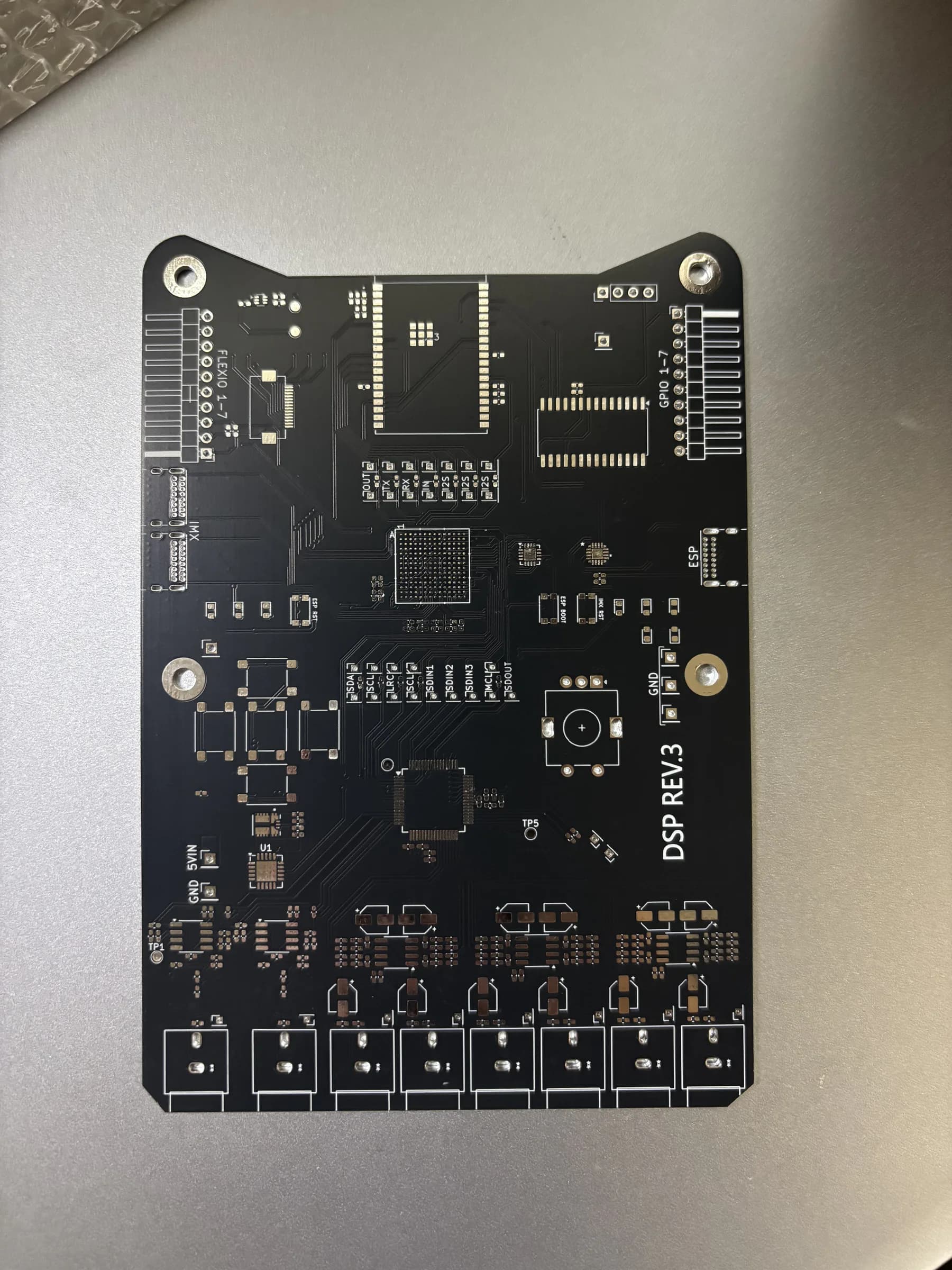
  • Front side of the fabricated black DSP Revision 3 PCB before assembly.
    Fabricated front side before population.
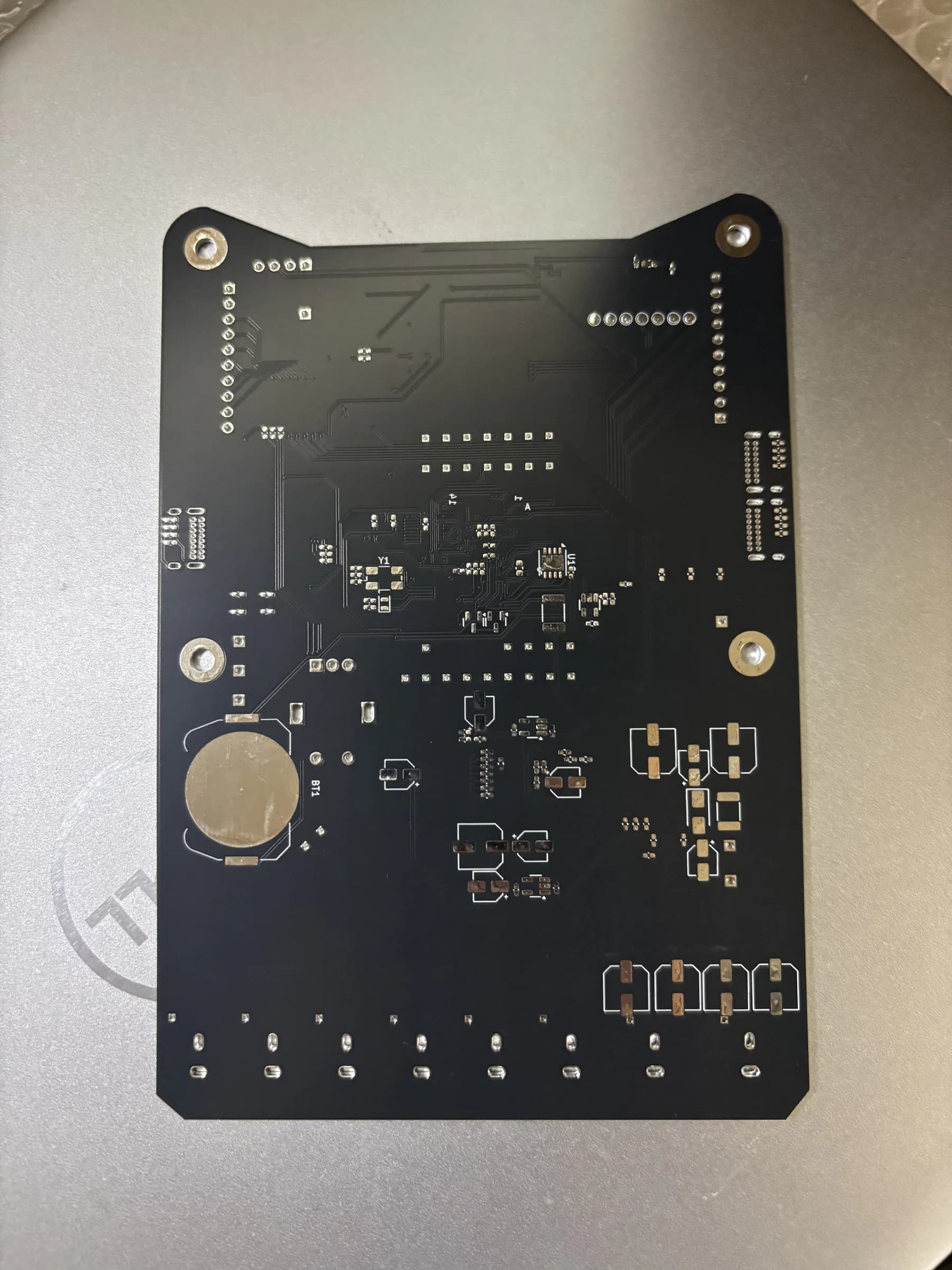
  • Back side of the fabricated DSP Revision 3 PCB before assembly.
    Back-side pads and support circuitry.
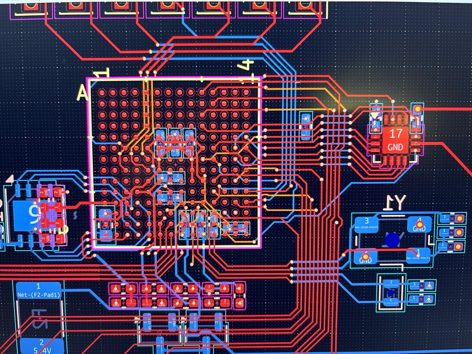
  • KiCad close-up of the densely routed i.MX RT1062 region on DSP Revision 3.
    i.MX RT1062 fanout and local support routing.
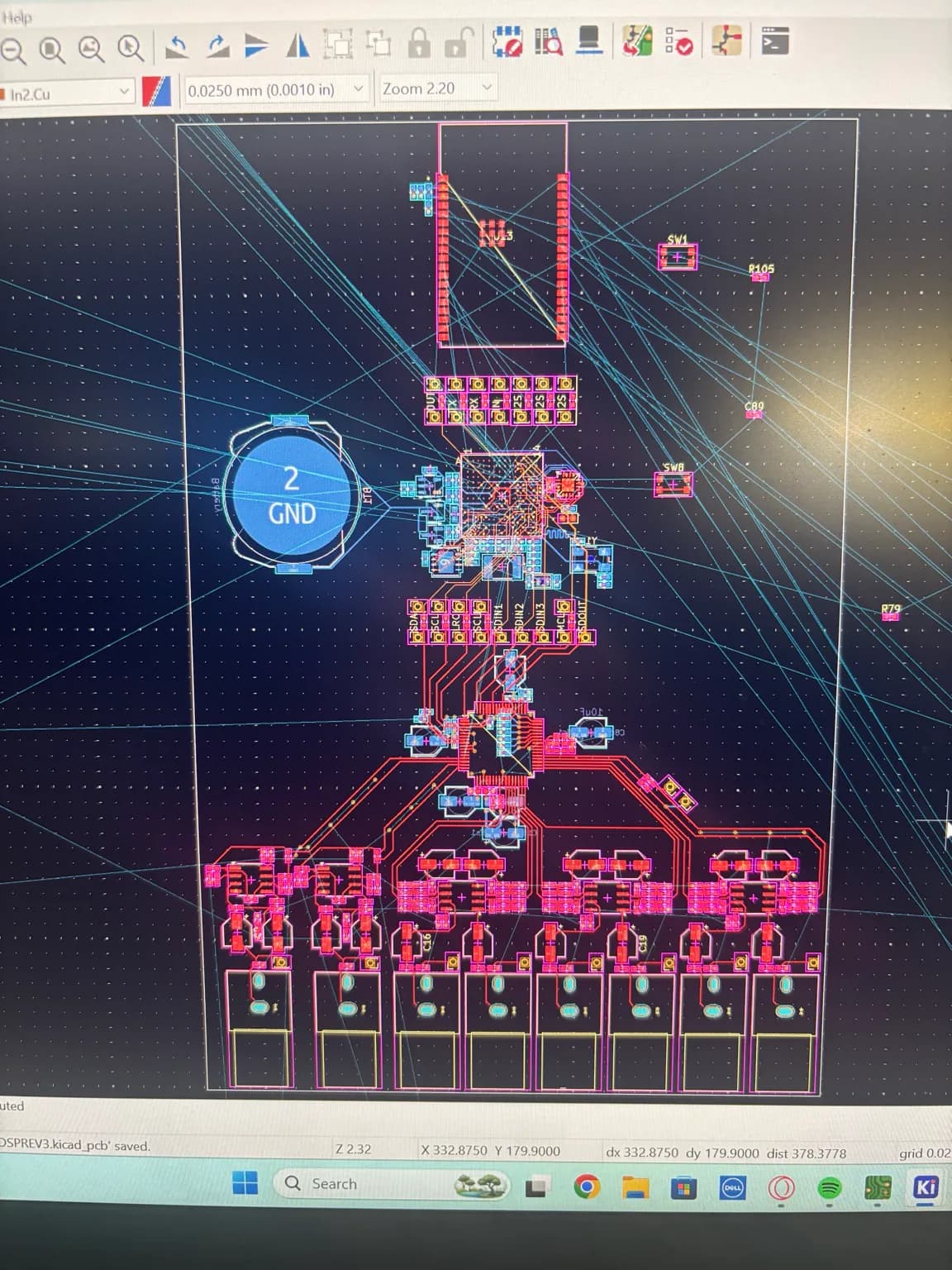
  • KiCad view showing the full DSP Revision 3 multilayer PCB layout.
    Full-board placement and multilayer routing.

What mattered

Rev 3 represents the transition from adapting existing controller hardware toward designing a more complete embedded audio system, while keeping the boundary between designed, assembled, and experimentally validated work explicit.

View full engineering case study
Project 04

Physical mockup + scan-derived mounting architecture

Final trim and installed acoustic validation are not claimed.

Custom A-Pillars — 2001 Honda Accord

Built custom A-pillars for a Focal Flax three-way audio system, placing the midranges near ear level and angling them to raise and level the soundstage. When a conventional 3D scan repeatedly failed on the large featureless trim, I developed a sectional scan, alignment, cleanup, and reconstruction workflow to turn the factory pillar into clean editable geometry.

Tools / Processes

  • Revopoint POP 3
  • Blender
  • Fusion 360
  • 3D printing
  • Scan preparation
  • Multi-scan alignment / stitching
  • Mesh cleanup / repair
  • Retopology / surface reconstruction
  • Iterative fitment

Process record 06

Drag, swipe, or scroll horizontally

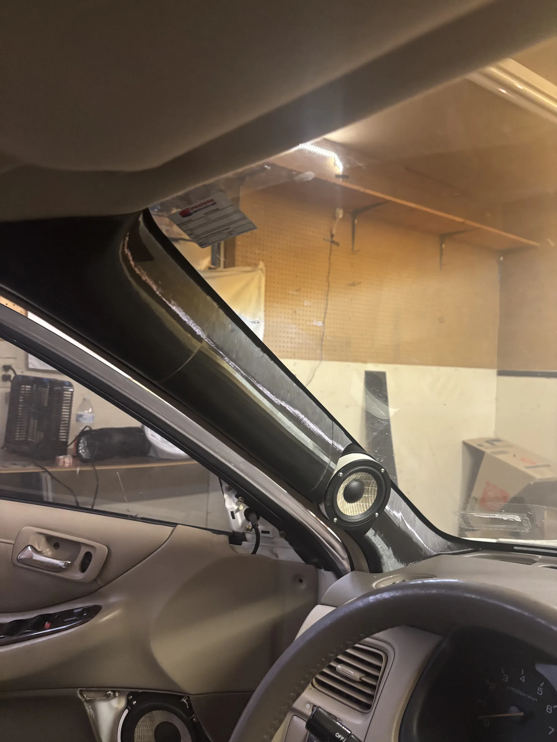
  • Physical midrange-positioning mockup mounted at the A-pillar of a 2001 Honda Accord.
    Physical positioning mockup in the vehicle.
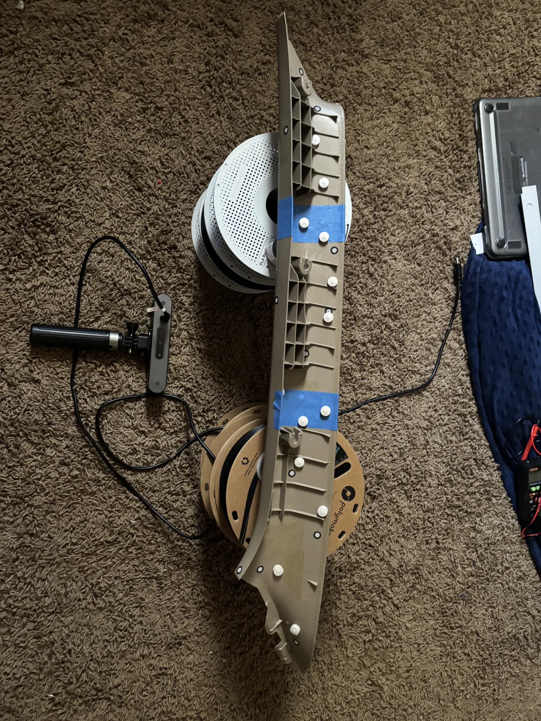
  • Factory A-pillar trim prepared with blue tape and physical tracking markers for scanning.
    Scan preparation with custom physical tracking markers.
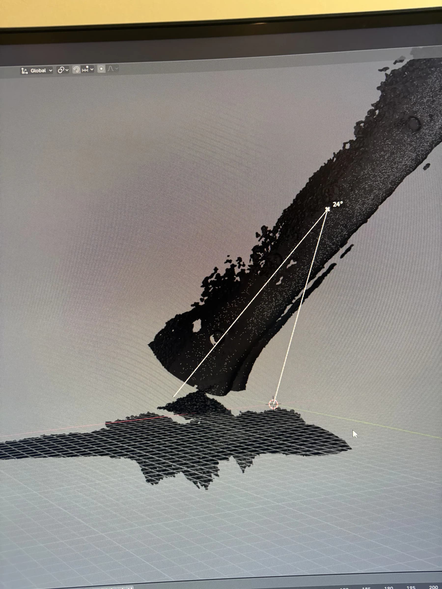
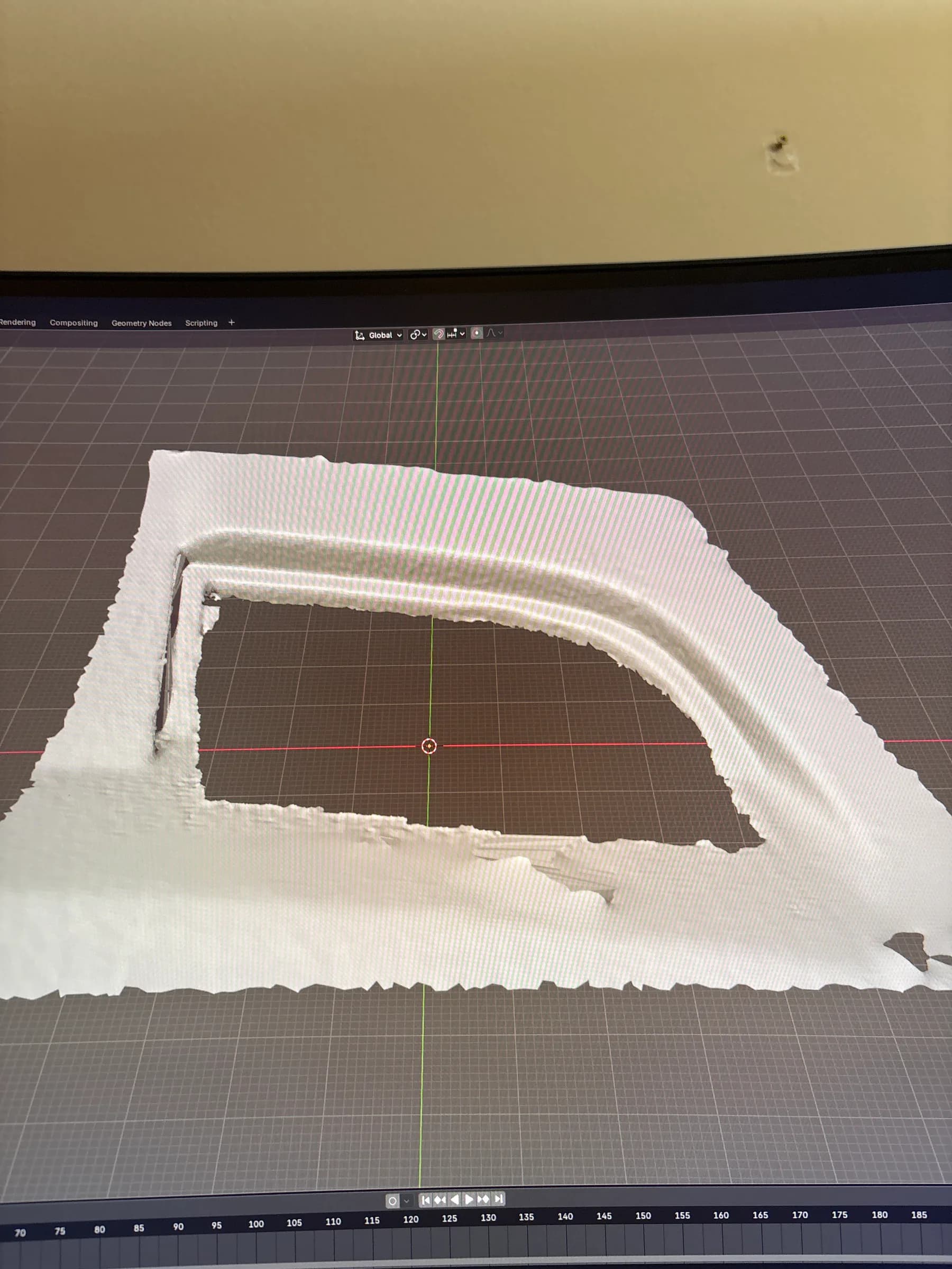
  • Noisy unaligned sectional scans of the factory A-pillar in Blender.
    Raw, noisy, and unaligned sectional scan data.
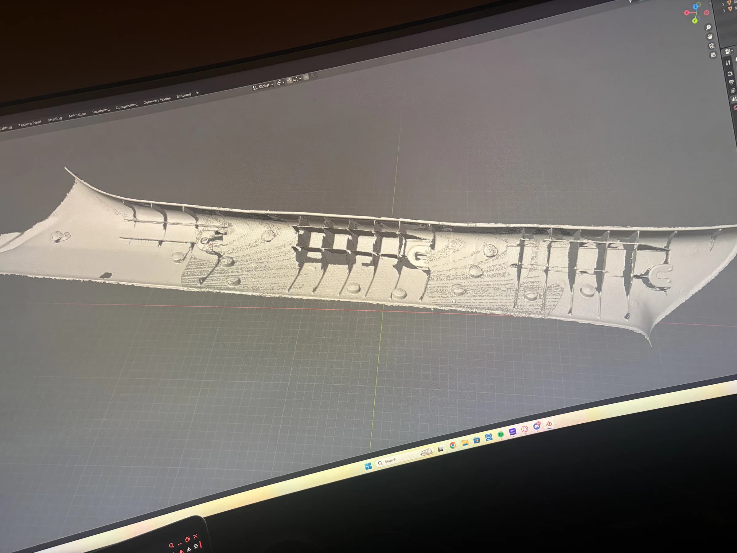
  • Multiple A-pillar scan sections aligned into one reference mesh in Blender.
    Overlapping sections after controlled alignment.
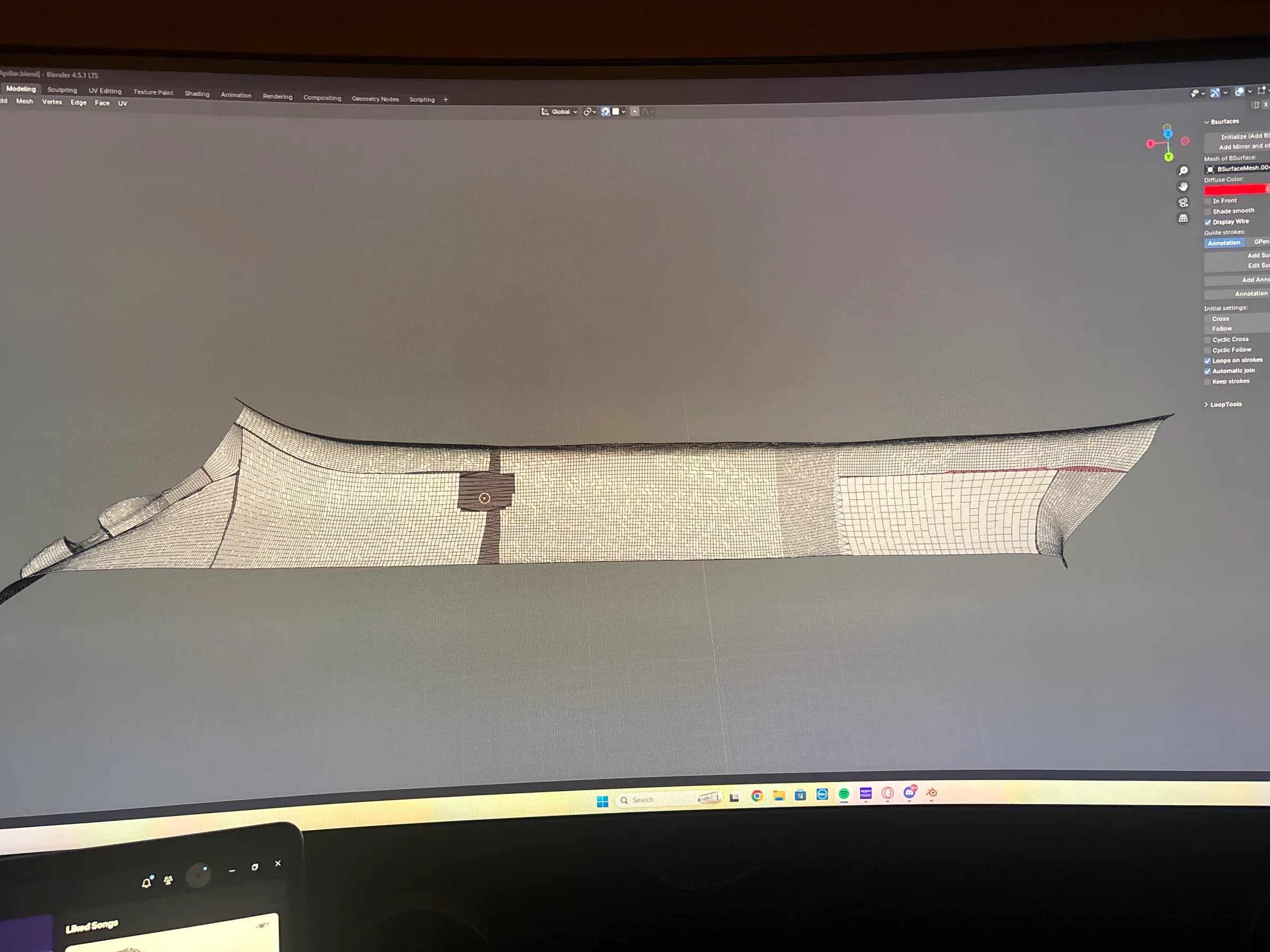
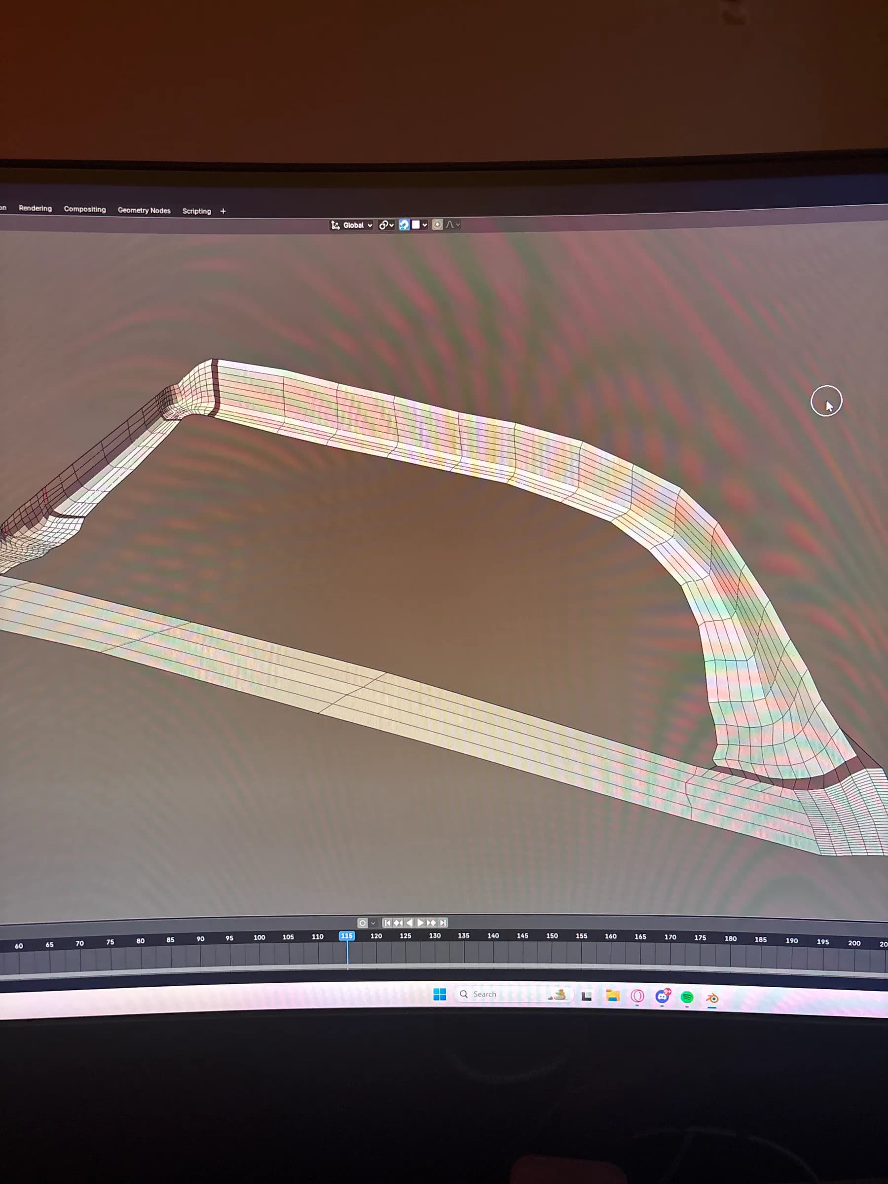
  • Cleaned A-pillar mesh reconstructed from the aligned scan sections.
    Aligned scan after mesh cleanup and repair.
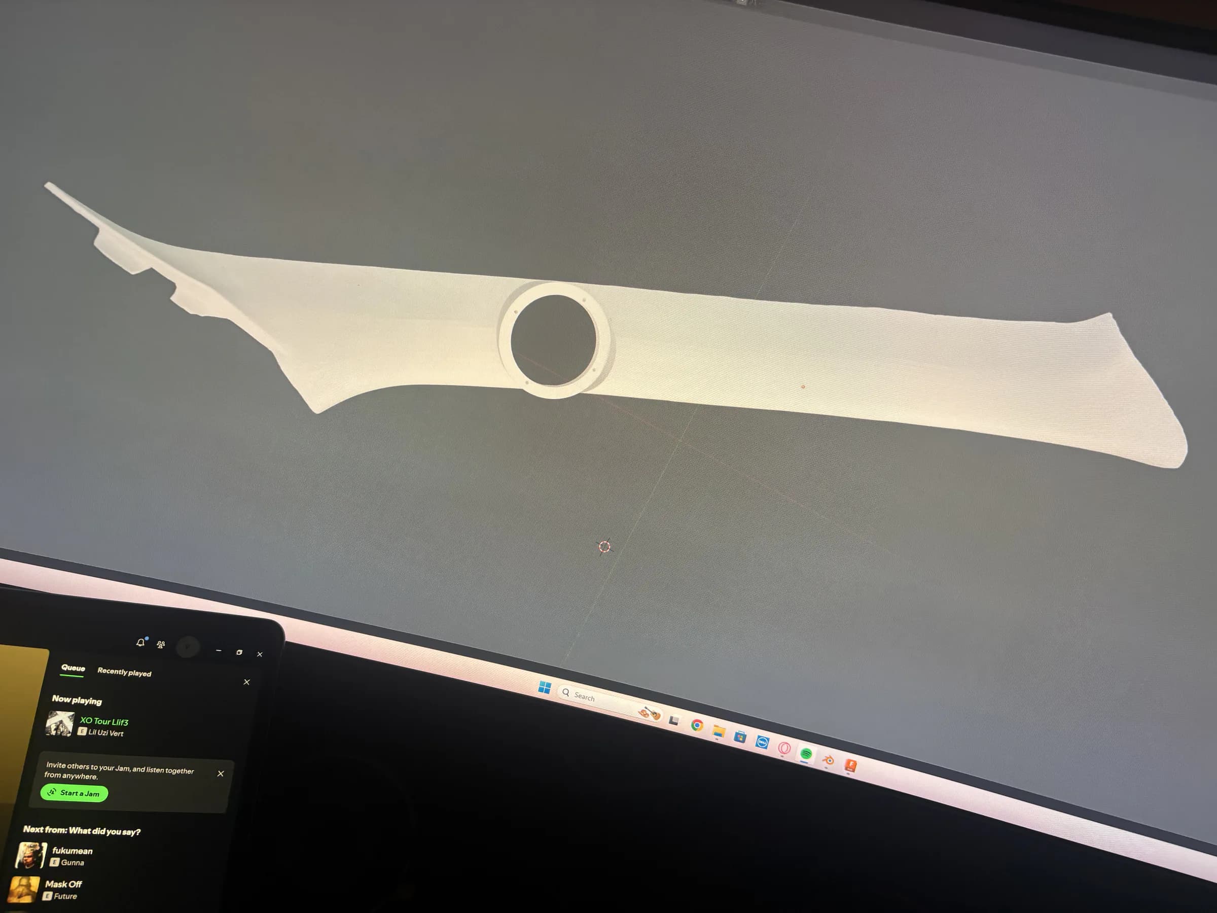
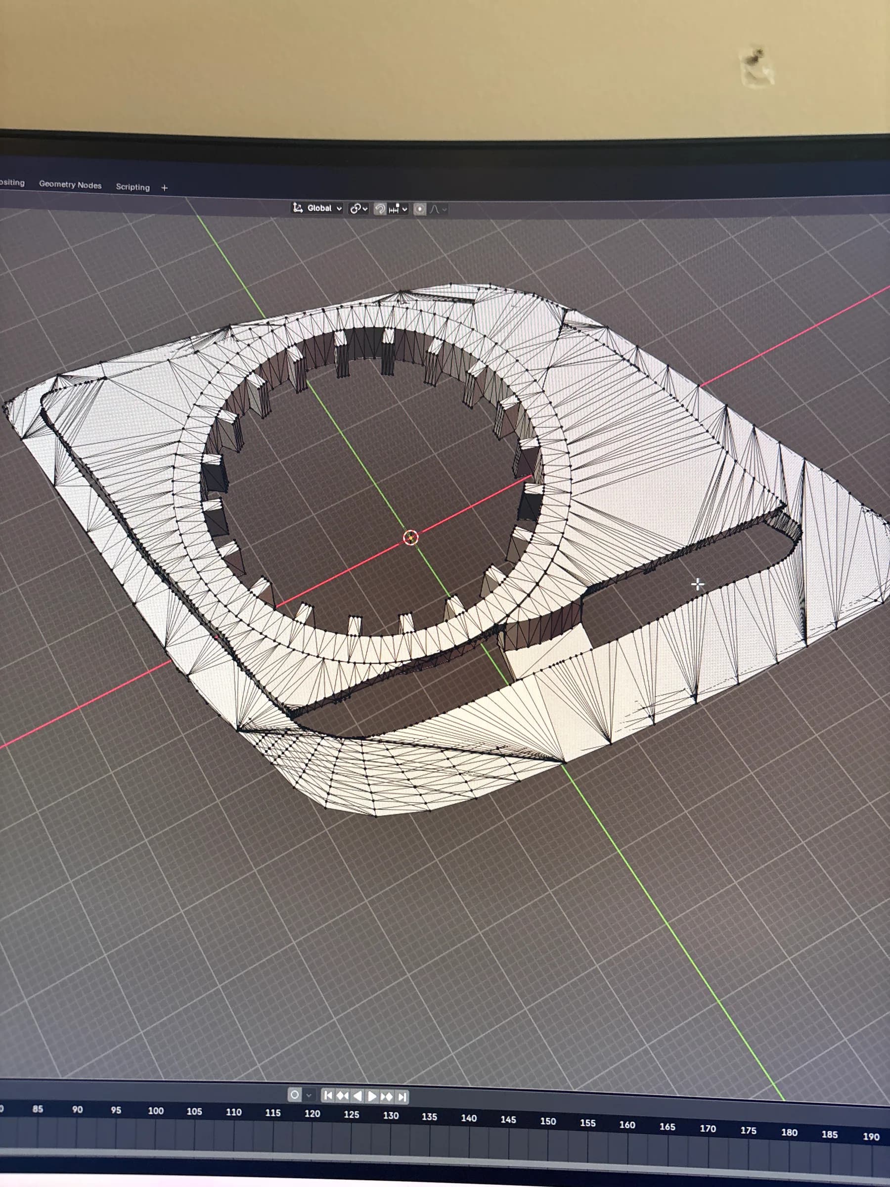
  • Final editable A-pillar surface model with an integrated circular speaker opening.
    Final editable surface model and speaker opening.

What mattered

  1. Failed scanning
  2. Physical tracking markers
  3. Overlapping sectional scans
  4. Controlled alignment
  5. Mesh reconstruction
  6. Speaker-ready solid geometry

The important result was a repeatable path from unreliable scan data to clean solid geometry that could accept integrated speaker mounts.

Project 05

10–20 revisions / limited small-batch sales

6.5-inch Speaker Adapter

What began as a crude hand-measured spacer became a 10–20 revision product-development project focused on exact fitment, window-track clearance, hardware tolerances, material selection, printability, and finish quality. The design progressed from paper templates and bulky PLA/PETG prototypes to scan-derived geometry, threaded inserts, and a refined ABS version with a repeatable vapor-smoothed finish.

Tools / Processes

  • Fusion 360
  • 3D scanning
  • 3D printing
  • PLA / PETG / ABS iteration
  • Threaded inserts
  • Fit / tolerance testing
  • Sanding / filler / paint / clear-coat experiments
  • UV-resin finishing
  • Custom leveling / drying setups
  • ABS vapor smoothing

Process record 07

Drag, swipe, or scroll horizontally

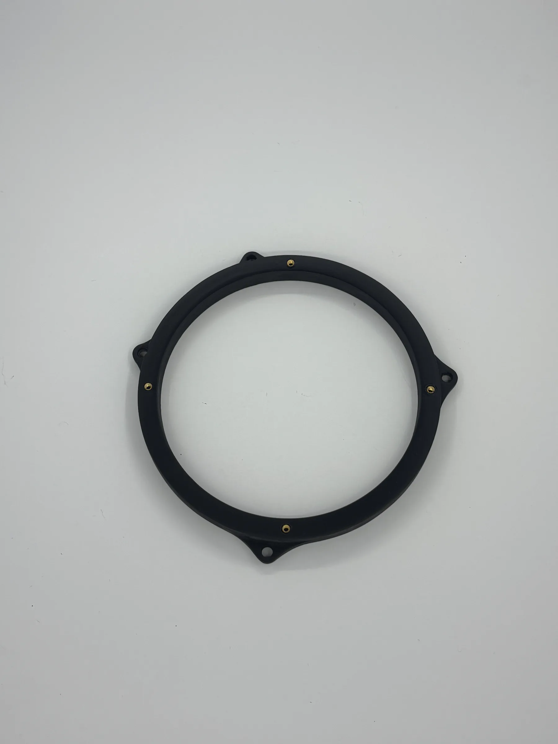
  • Finished matte-black 6.5-inch speaker adapter with four brass threaded inserts on a white surface.
    Finished geometry, threaded inserts, and a clean final-part presentation.
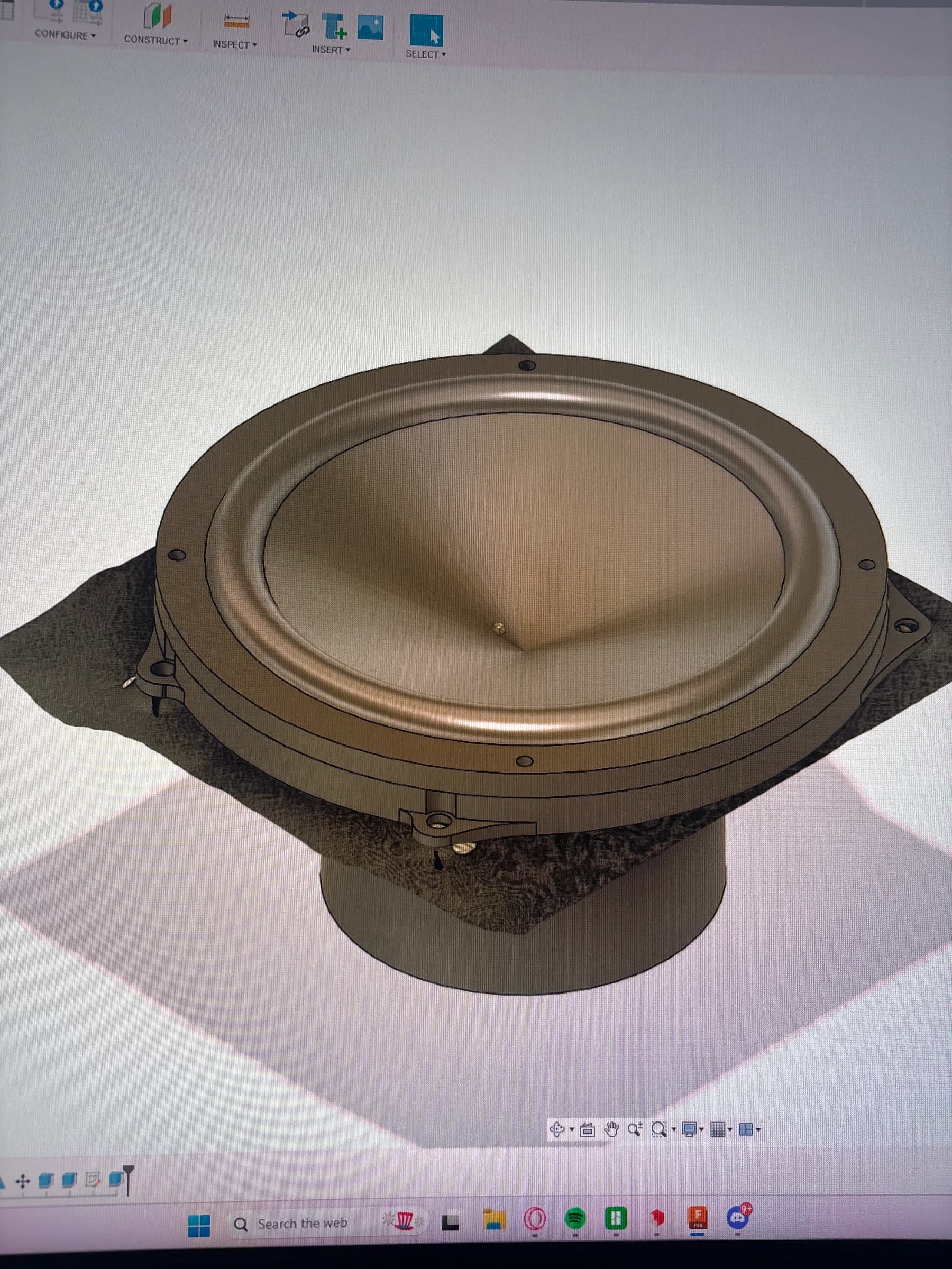
  • Fusion 360 model of the scan-derived 6.5-inch speaker adapter geometry.
    Scan-derived geometry rebuilt in Fusion 360.
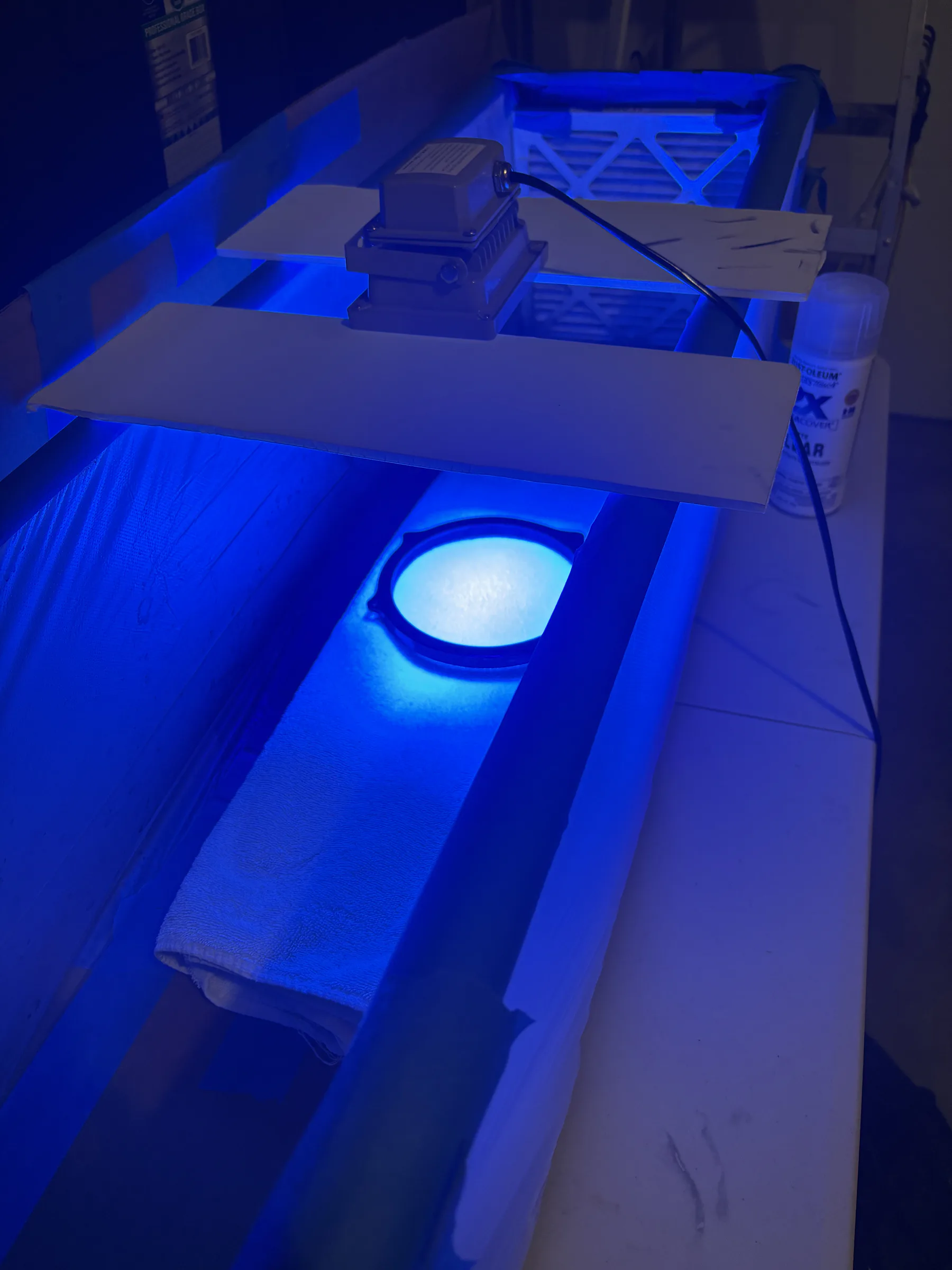
  • A speaker adapter curing beneath ultraviolet lights during a resin-finish experiment.
    UV-resin finishing experiment and curing setup.
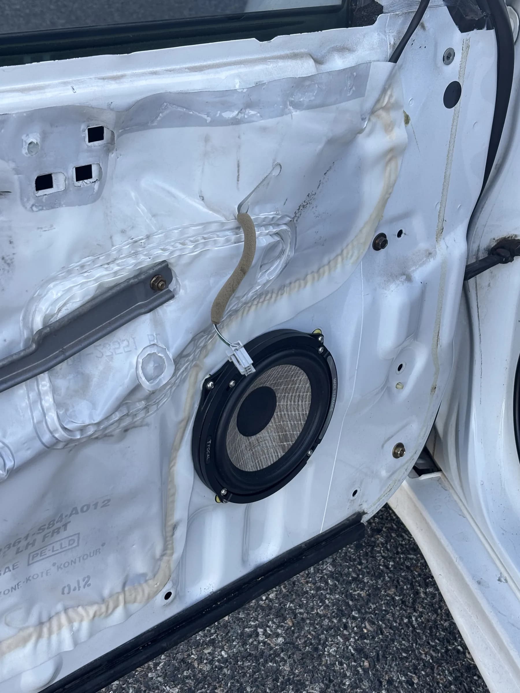
  • 6.5-inch speaker and custom adapter installed inside the Honda Accord door.
    Door fitment and window-track clearance check.
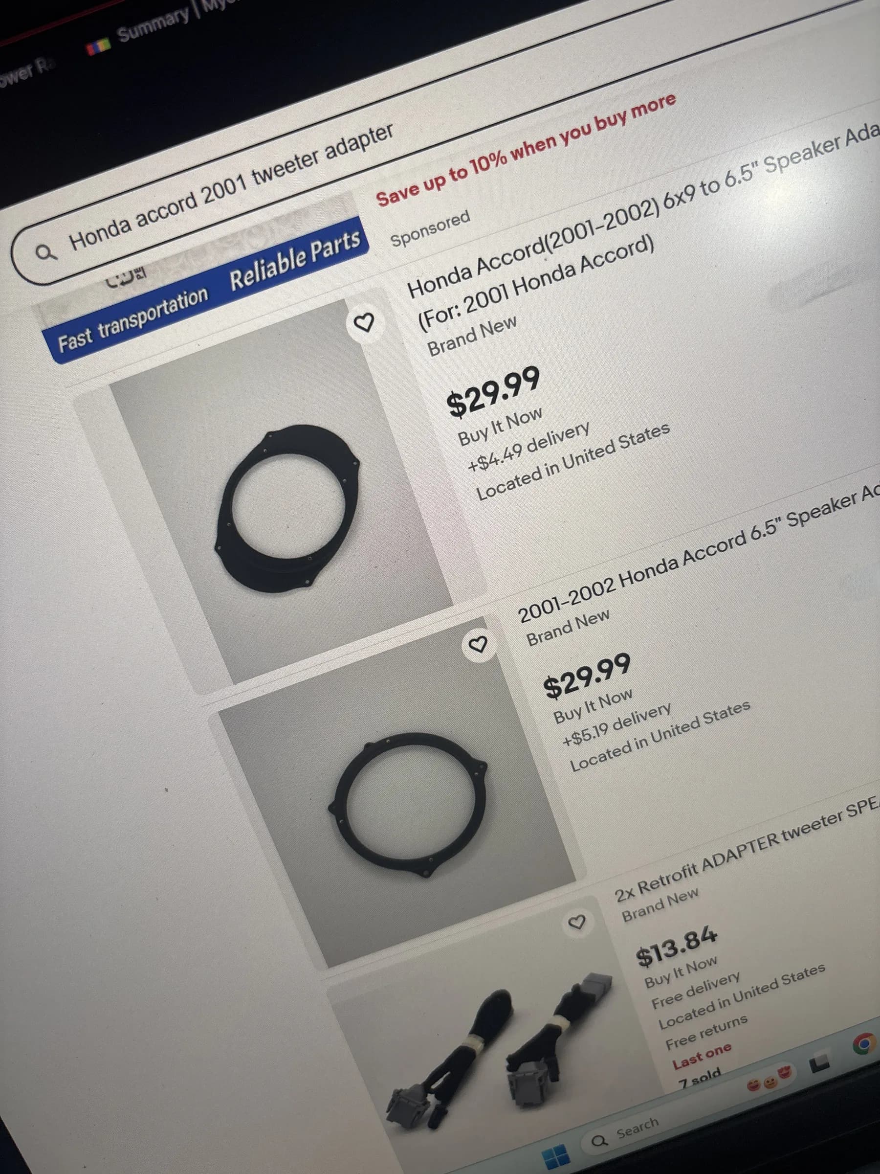
  • Marketplace results showing two $29.99 Honda Accord speaker-adapter listings above an unrelated product marked seven sold.
    Two $29.99 adapter listings; the visible ‘7 sold’ belongs to the unrelated result below.
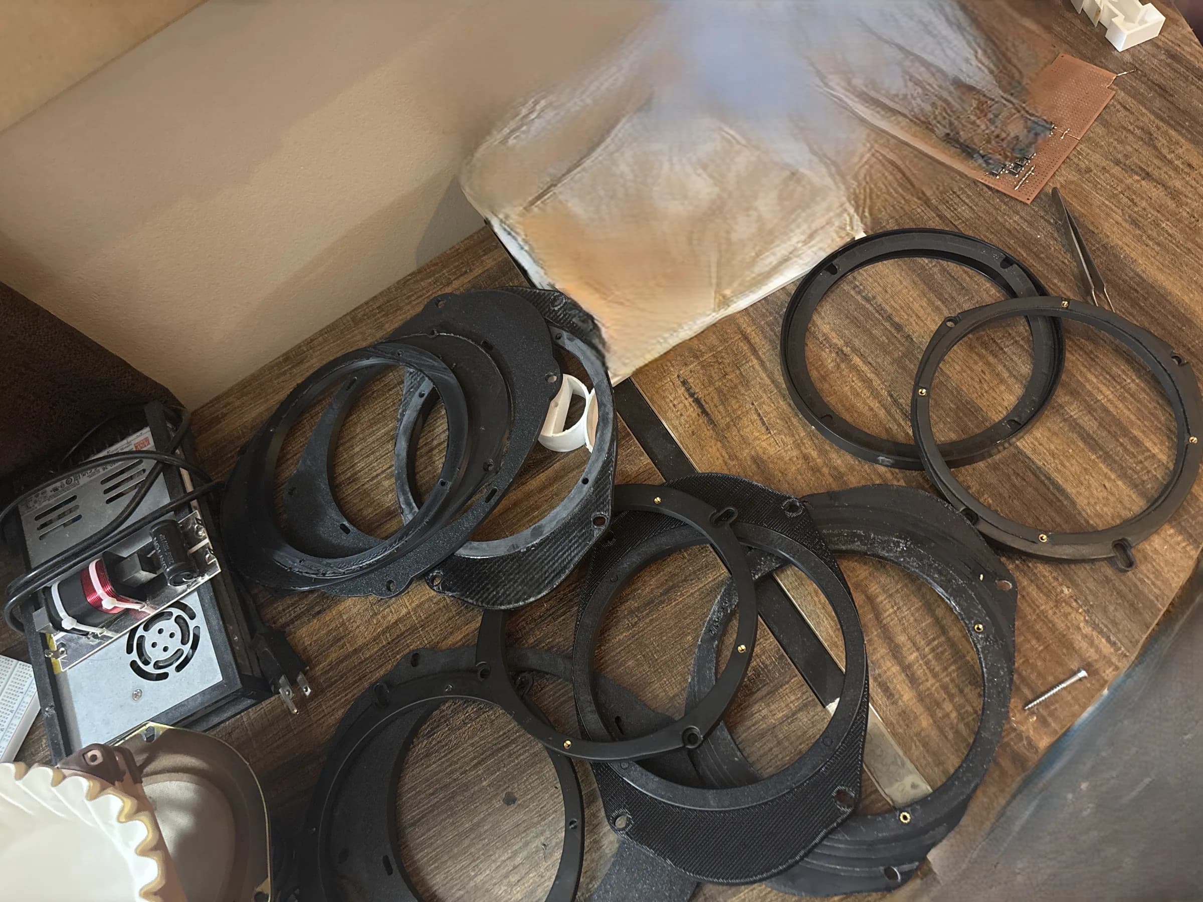
  • Pile of 3D-printed 6.5-inch speaker adapter revisions from repeated fitment testing.
    The physical revision pile—fitment learned in plastic.
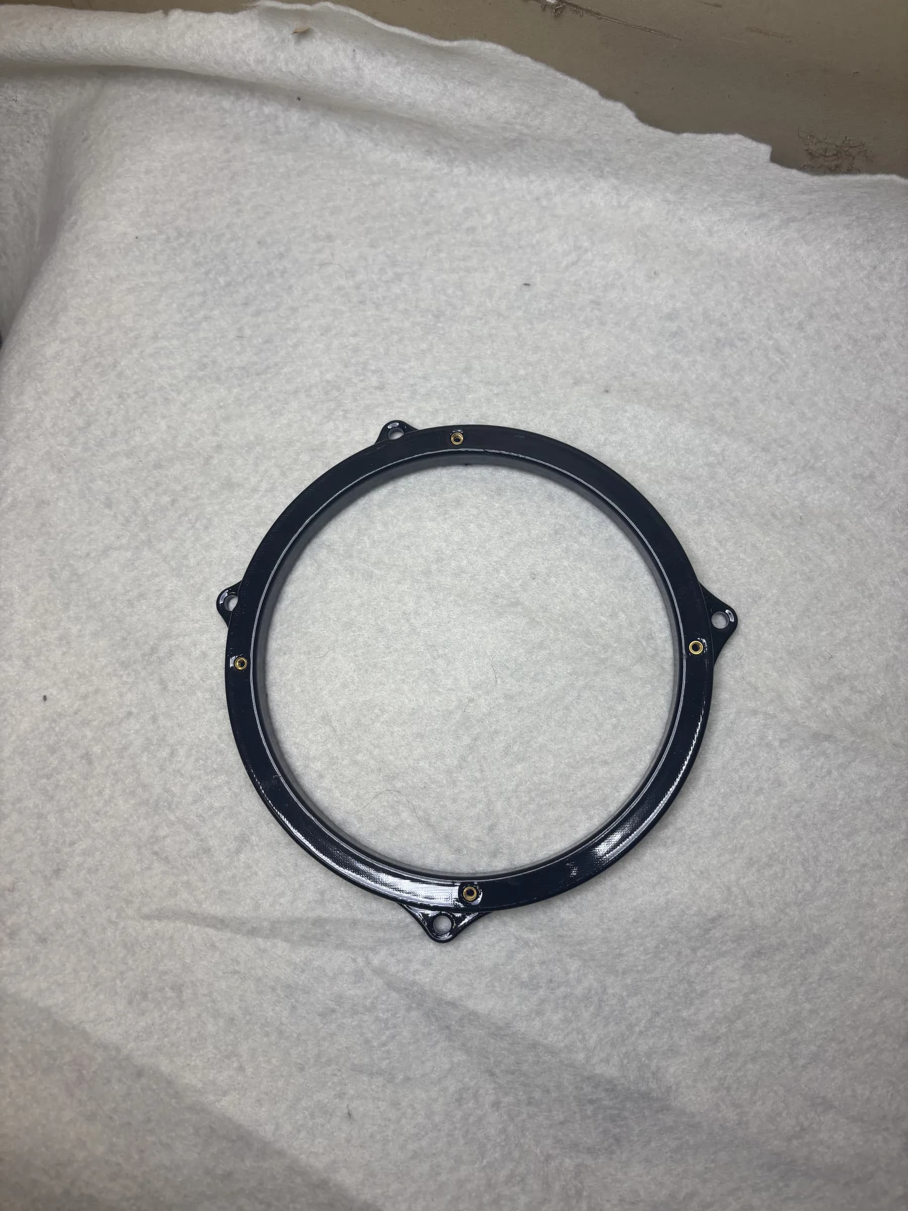
  • Glossy black ABS 6.5-inch speaker adapter after a vapor-smoothing finish experiment.
    Vapor-smoothed ABS at the end of the finishing process.

What mattered

Making one part fit is very different from making something repeatable, durable, visually clean, printable, easy to finish, and product-ready. A large part of the project became process engineering rather than CAD alone.

Limited validation only: approximately ten satisfactory adapters were sold at around $30 each.

Project 06

Iterative fitment complete / PETG-CF final material

Tweeter Adapter

Started with phone photos and paper tracing to approximate the factory tweeter geometry, then rebuilt the design around 3D scans of the tweeter pocket and OEM holder. After manually repairing and retopologizing the scan, I used the reconstructed shell as a mold reference in Fusion 360 to create a precise adapter with integrated clips and reinforcement.

Tools / Processes

  • 3D scanning
  • Blender
  • Fusion 360
  • Manual mesh repair
  • Retopology
  • Mold / subtraction modeling
  • 3D printing
  • PETG / PETG-CF
  • Iterative fitment testing

Process record 07

Drag, swipe, or scroll horizontally

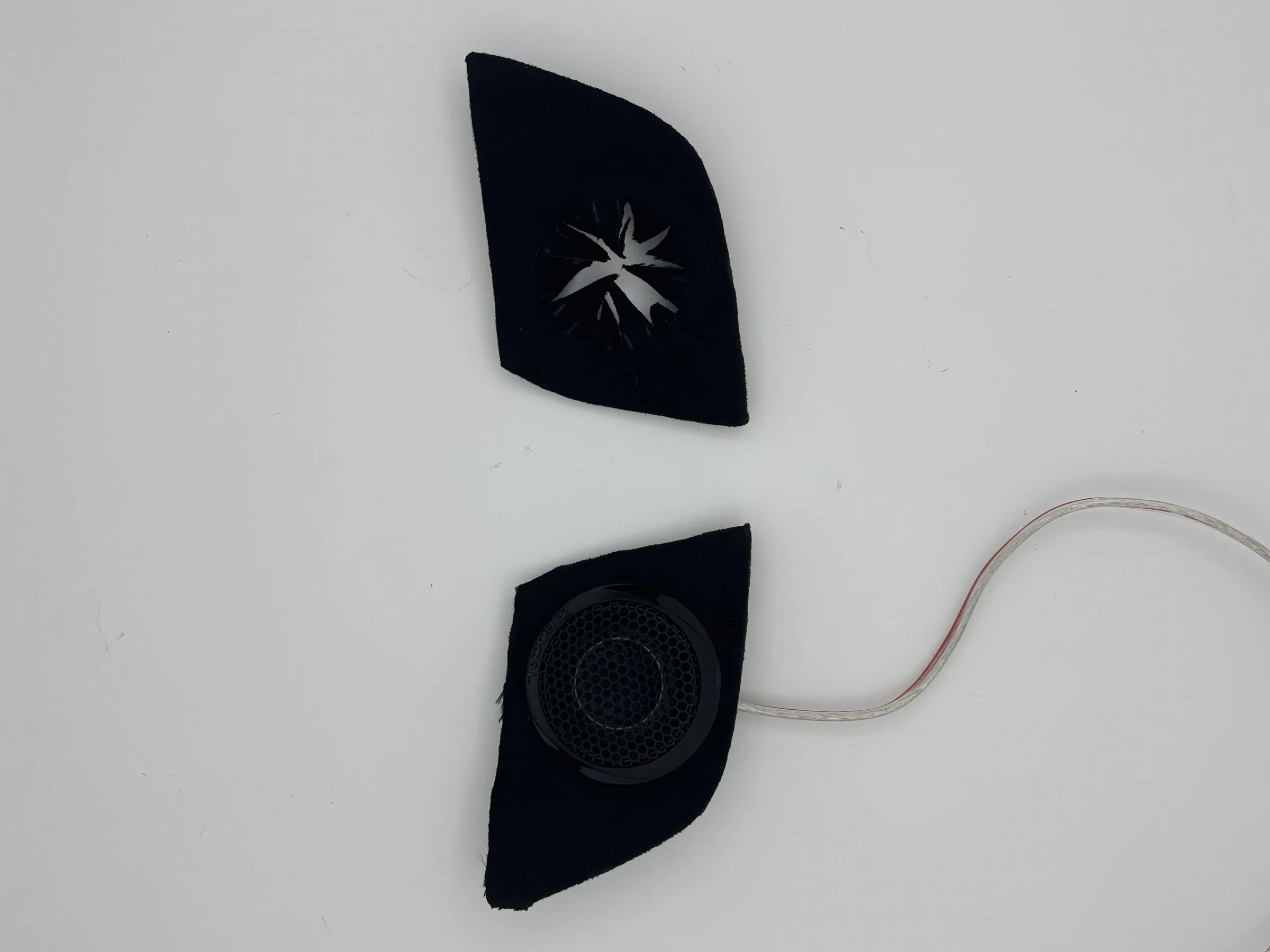
  • Finished black tweeter adapter shown beside the fitted tweeter assembly.
    Finished adapter and fitted tweeter assembly.
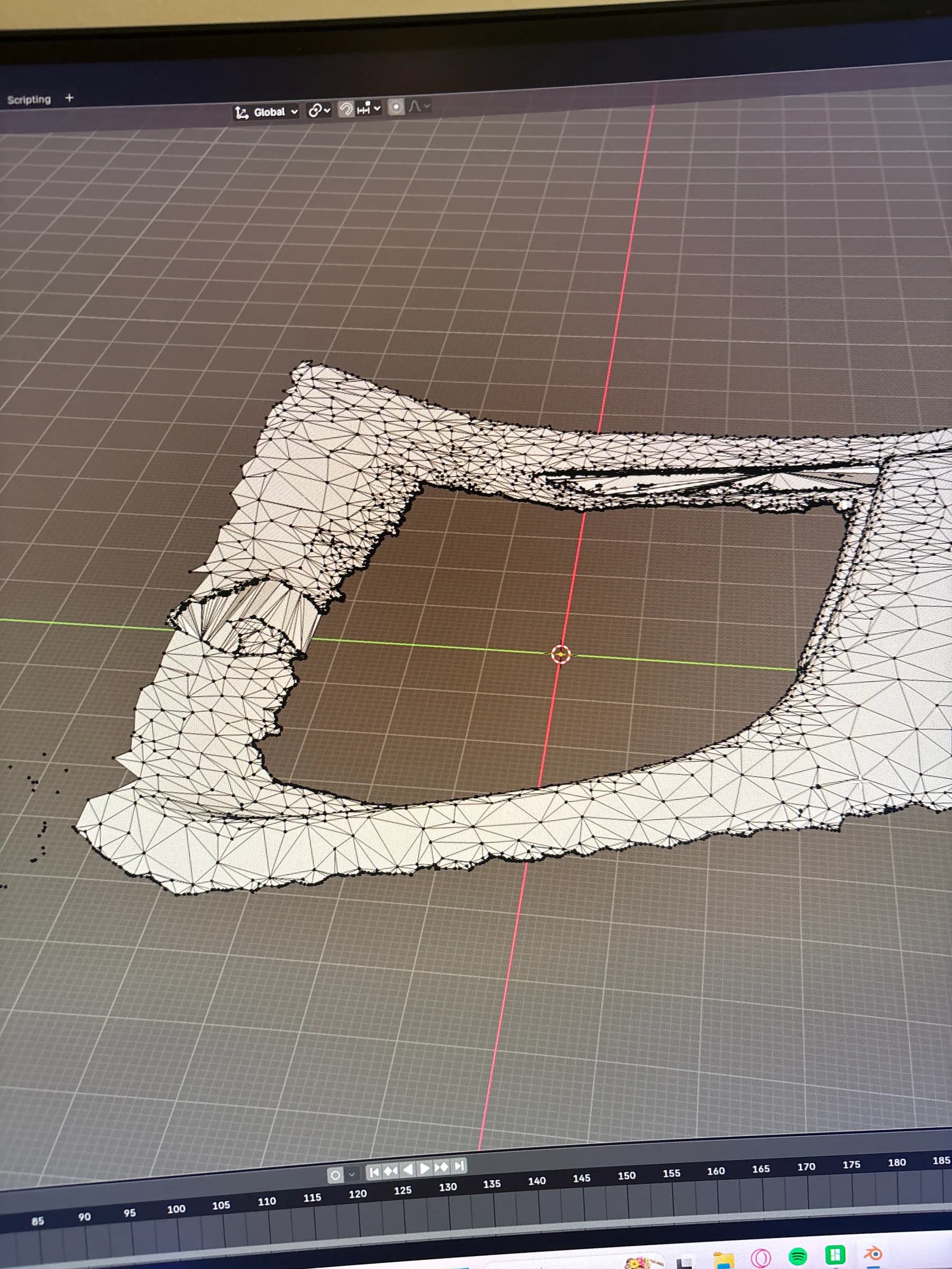
  • Raw 3D scan of the factory tweeter pocket shown in Blender.
    Raw pocket scan with incomplete edge geometry.
  • Dense noisy tweeter-pocket mesh being repaired and retopologized in Blender.
    Manual mesh repair and retopology.
  • Clean reconstructed shell matching the factory tweeter pocket geometry.
    Clean shell reconstructed from the scan.
  • CAD model of the tweeter adapter with radial clips and reinforced retention geometry.
    Mold-derived body with integrated retention clips.
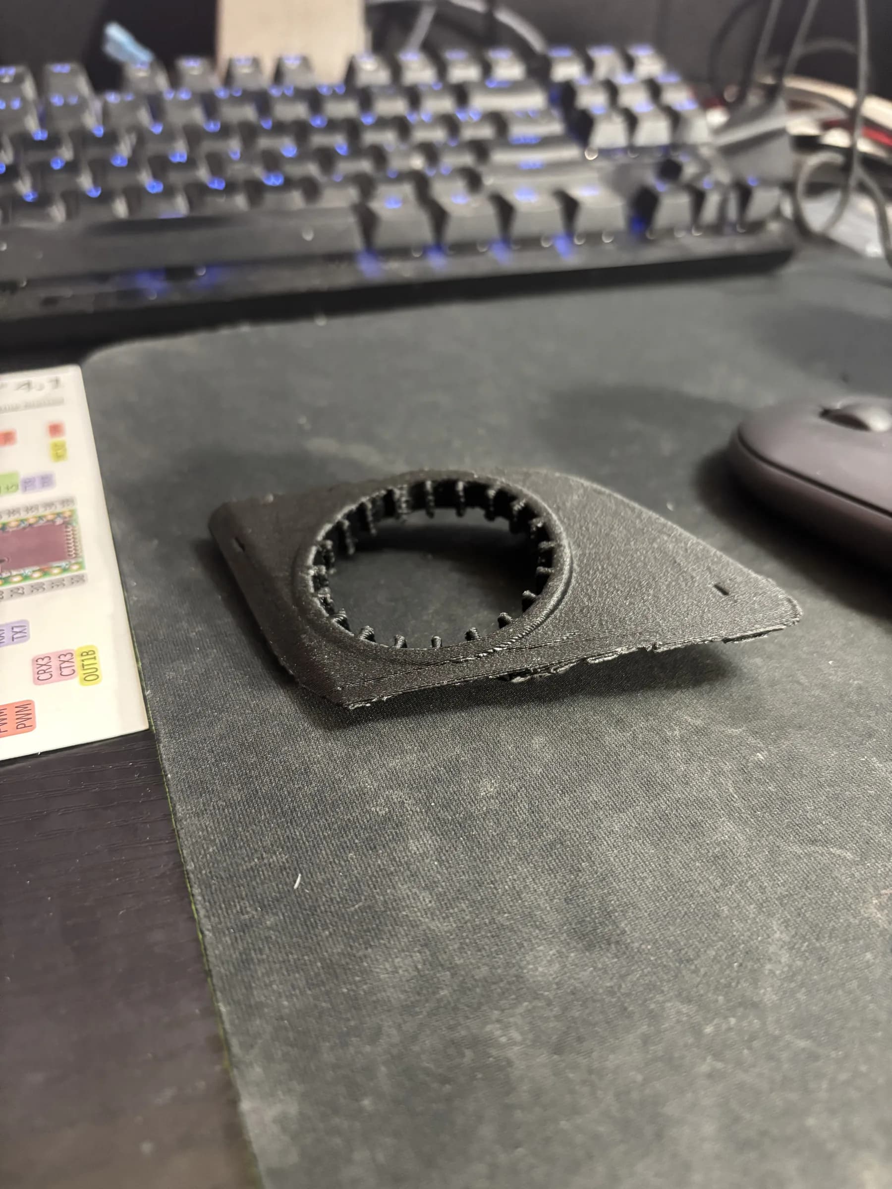
  • Black 3D-printed tweeter adapter revision on the workbench.
    Printed revision after clip reinforcement.
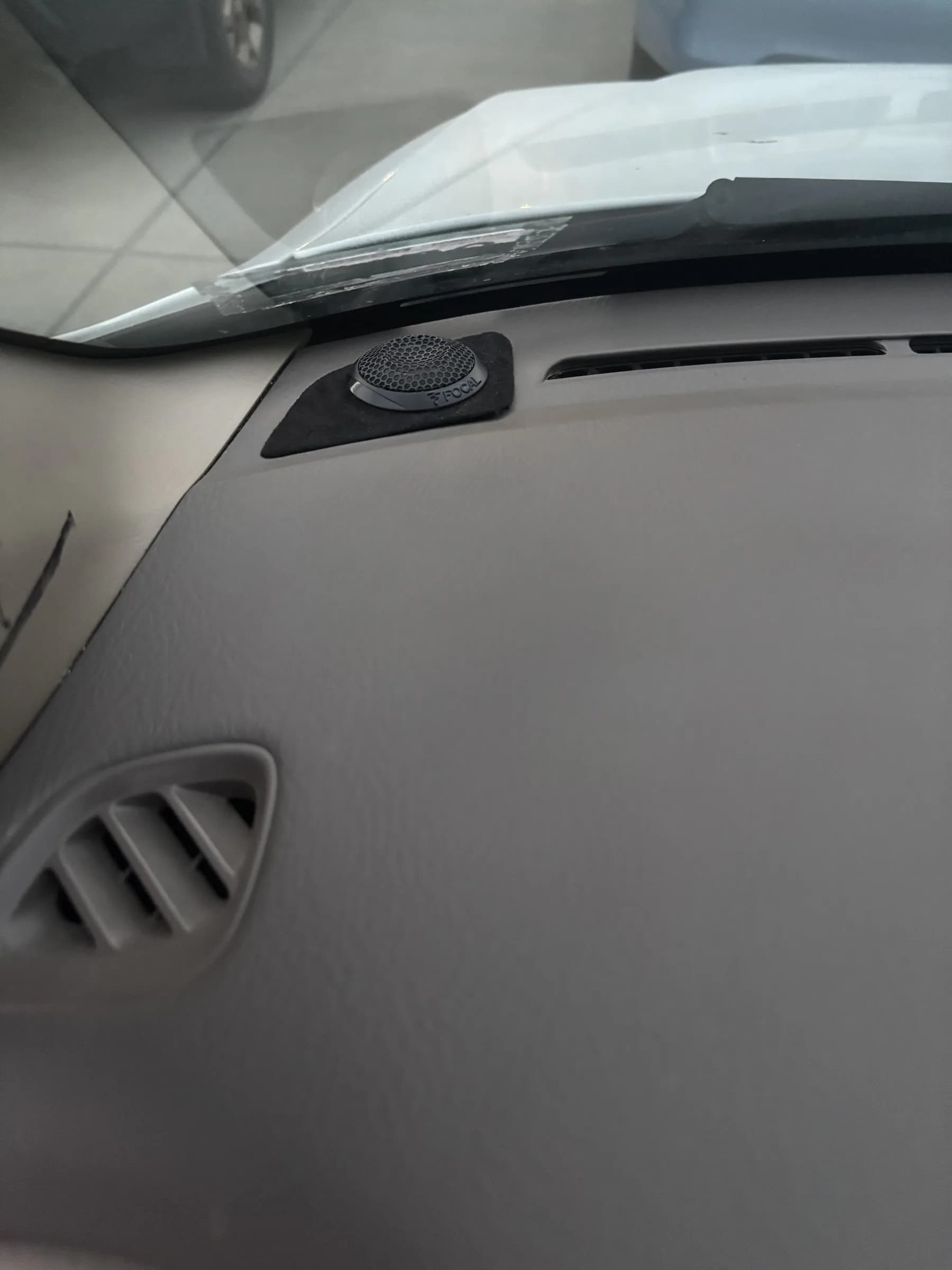
  • Tweeter installed flush in the factory Honda Accord dashboard pocket.
    Final installed fitment in the factory pocket.

What mattered

Standard PETG clips repeatedly snapped during installation and removal, so the retention geometry was reinforced and the material was changed to PETG-CF for greater rigidity and durability.